
Jul 22, 2026Case Studies & Applications
What's the Right Carbide End Mill Feed Per Tooth?
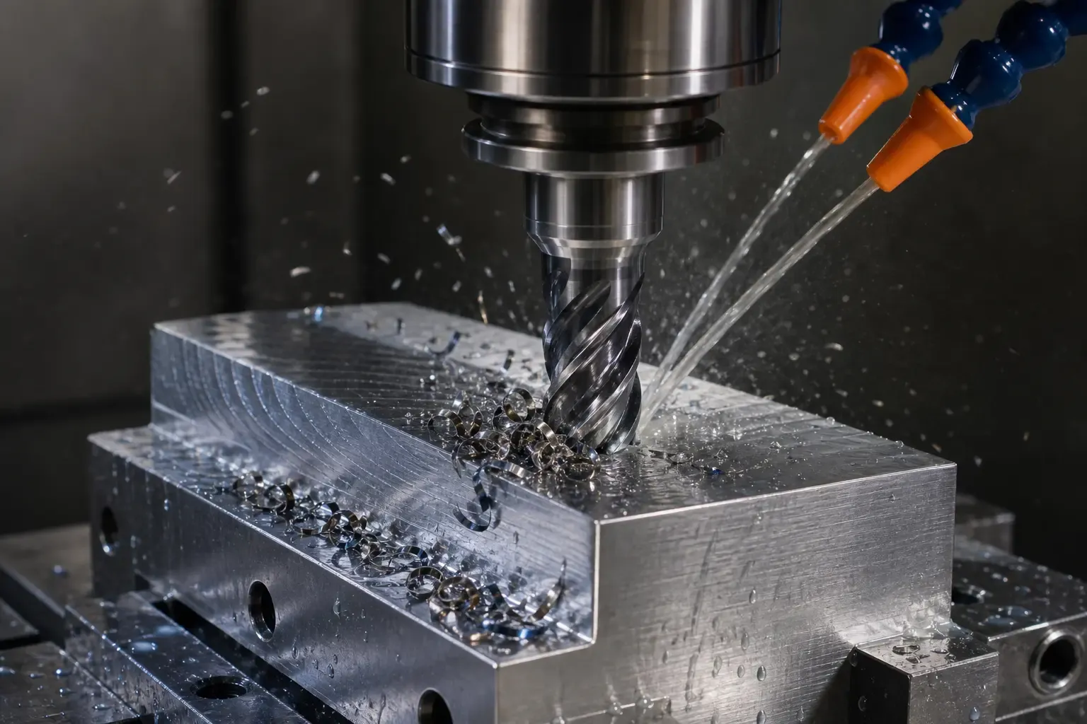
Struggling to find the single "correct" carbide end mill feed per tooth for your job? It's a common frustration. Using the wrong value can lead to snapped tools, a terrible surface finish, and wasted time and money. The solution isn't to find a magic number, but to reframe the question and understand the key variables that determine your optimal starting point.
The ideal carbide end mill feed per tooth is not a single, universal value but a calculated starting point that balances multiple factors.[1] It primarily depends on the workpiece material, tool diameter, number of flutes, and the specific application (e.g., roughing vs. finishing). Manufacturer charts provide this baseline, which must then be adjusted based on your machine's condition, workholding, and real-world feedback.
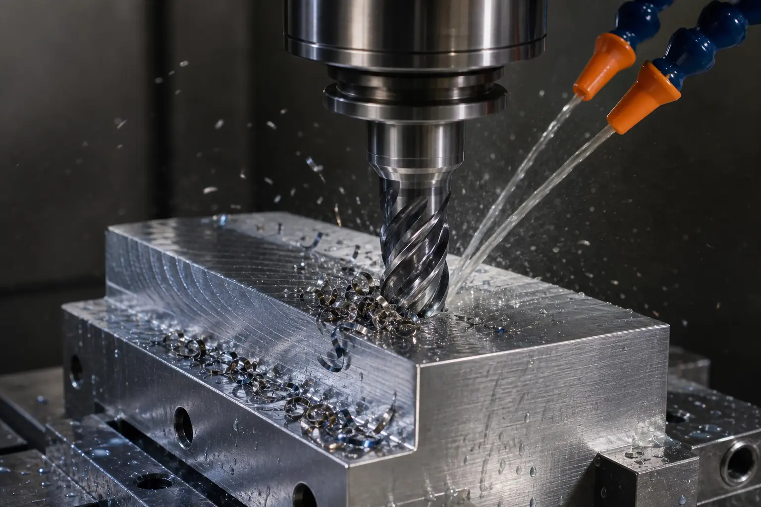
Now that we've established that feed per tooth is a dynamic starting point, not a fixed rule, let's dive into how you can determine and refine that number. This knowledge will empower you to balance performance, extend tool life, and ultimately lower your cost per part.
How Do Manufacturer Charts Define the Carbide End Mill Feed Per Tooth?
Do you treat the speed and feed charts that come with your tools as absolute rules? A common question we get from customers is why their real-world results don't perfectly match the numbers on paper. This leads to frustration, but the issue lies in a misunderstanding of the chart's purpose. The solution is to see them for what they are: a safe, conservative starting point.
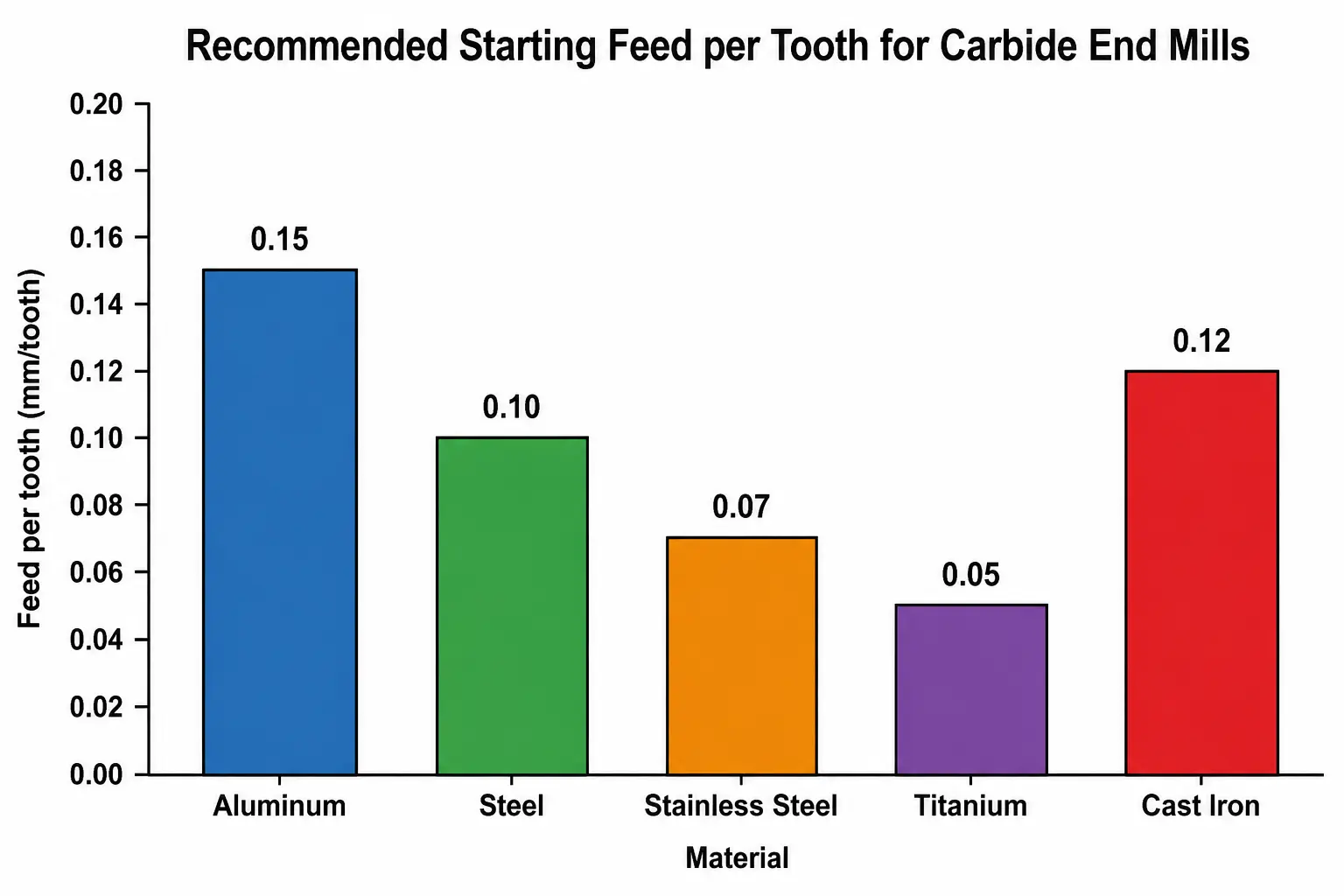
Manufacturer charts provide recommended starting values for carbide end mill feed per tooth based on the tool's geometry and the general category of material being cut.[2] These are not guarantees of maximum performance but are instead conservative baselines developed under ideal, controlled laboratory conditions.
Dive Deeper: From the Chart to the Shop Floor
As a tool supplier, I've seen firsthand how a chart can be both helpful and misleading if not interpreted correctly. The numbers in a catalogue are your first step, not your final destination. They represent a scientifically derived baseline that assumes a perfect world—something that rarely exists on a busy shop floor.
What the Chart Numbers Really Mean
When we or any other manufacturer create a chart, the tests are run under pristine conditions. This means:
- A brand new, highly rigid, and perfectly calibrated CNC machine.
- High-quality, balanced tool holders with minimal runout (wobble).
- Extremely secure and rigid workholding.
- Ideal coolant flow and concentration.
The carbide end mill feed per tooth listed is the value that proved effective and safe under those conditions. Your job is to assess how your environment differs and adjust accordingly.
Why Your Machine's Condition Matters
The single biggest variable a chart cannot account for is your machine. A 10-year-old machine with some wear on the box ways will not be as rigid as a new linear guide machine. This lack of rigidity introduces vibration (chatter), which is the enemy of any cutting tool.[3]
- Rigidity: If your machine is less rigid, you must decrease the feed per tooth to reduce cutting forces and prevent chatter.
- Spindle Horsepower: If a cut requires more power than your spindle can provide, the machine will bog down. This forces a reduction in either the depth of cut or the feed per tooth.
- Runout: If your tool holder or spindle has significant runout, the effective chip load on each tooth becomes uneven.[4] One flute may take a much larger bite than the others, leading to premature wear or tool breakage. In this case, a lower starting FPT is a necessary precaution.
The Role of Workholding
How you hold your part is just as important as the machine itself. I recall a customer who was breaking tools despite following our chart perfectly. After a brief discussion, we discovered their part was clamped in a vise with significant overhang. The workpiece itself was vibrating during the cut. By improving their workholding to support the part more rigidly, they were able to meet and even exceed the chart's recommendations.
Think of it this way: any instability in the system forces you to be more conservative with your carbide end mill feed per tooth.
What Key Factors Influence Your Starting Carbide End Mill Feed Per Tooth?
Feeling overwhelmed by all the variables that affect your feed rate? It's easy to get lost in the details, and guessing can be expensive. By focusing on a few key factors, however, you can move from guessing to making a calculated, informed decision about where to start.
The most critical factors influencing your starting carbide end mill feed per tooth are the workpiece material, the tool's diameter and number of flutes, and the depth of your cut (both axially and radially). Each of these elements requires a specific and logical adjustment to the baseline FPT from the chart.
Dive Deeper: A Practical Framework for Adjustment
The art of machining is knowing how to adjust for these variables. What customers often overlook is that these factors are interconnected. Changing one often requires you to change another. Here’s a practical framework we use when advising buyers.
H3: Workpiece Material Hardness and Abrasiveness
This is the most fundamental factor. The harder and more abrasive the material, the more stress it puts on the cutting edge.[5] Therefore, you must reduce the chip load to preserve the tool.
- Soft Materials (e.g., Aluminum, Brass): These materials are easy to cut. You can typically increase your feed per tooth from the baseline to maximize your material removal rate.
- Medium Materials (e.g., Low-Carbon Steel, Pre-Hardened Steels): This is often the baseline material group for many charts. You can generally start with the recommended value.
- Hard/Abrasive Materials (e.g., Stainless Steel, Tool Steel, Inconel): These materials generate significant heat and pressure. You must decrease the feed per tooth to prevent the cutting edge from chipping or failing prematurely.
Material Group | General Hardness | Recommended FPT Adjustment | Why? |
|---|---|---|---|
Aluminum & Alloys | Soft | Increase from baseline | Lower cutting forces allow for a larger chip. |
Low-Carbon Steel | Medium | Use baseline as a start | The standard against which many tools are tested. |
[Stainless Steels | Hard & Gummy | Decrease from baseline | Prone to work-hardening; a smaller chip reduces force.]( ] |
Hardened Steels (>45 HRC) | Very Hard | Significantly Decrease | Protects the fragile cutting edge from extreme pressure. |
H3: Tool Diameter and Flute Count
The physical size and design of the end mill are critical.
- Diameter: A larger diameter tool is inherently stronger and more rigid.[7] It can handle higher cutting forces, and thus a higher feed per tooth. A small-diameter tool (e.g., 1/8" or 3mm) is far more delicate and requires a much smaller FPT to avoid snapping.
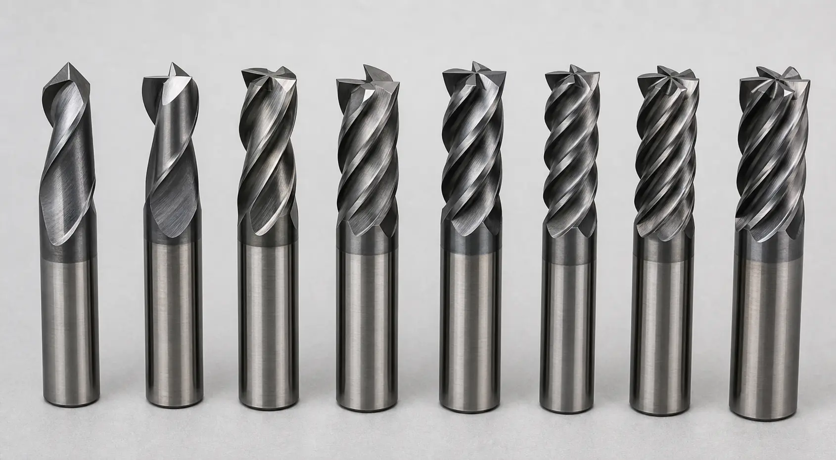
- Flute Count: This is a point of common confusion. A higher flute count (e.g., 5 or 7 flutes) does not mean you should use a higher feed per tooth. In fact, the FPT per individual tooth often needs to be slightly lower because there is less space (flute gullet) for chips to evacuate.[8]
The real advantage of more flutes is a higher table feed rate. The formula for feed rate is:
Feed Rate (IPM or mm/min) = RPM x FPT x Number of Flutes[9]So, even with a slightly lower FPT, multiplying by more flutes results in a faster overall cut, which is ideal for finishing passes.
H3: Axial and Radial Depth of Cut (DOC)
How much material the tool is engaged in directly impacts the load.
- Axial DOC (ADoc): The depth of the cut along the tool's axis.
- Radial DOC (RDoc): The width of the cut, or how much the tool is stepping over.
A deep axial cut combined with a wide radial cut (like full-width slotting) puts maximum strain on the tool. In this scenario, you must reduce your feed per tooth significantly. Conversely, modern "High-Efficiency Milling" (HEM) toolpaths use a very small radial DOC but a very deep axial DOC. This light radial engagement reduces cutting forces and heat, allowing you to dramatically increase your feed per tooth—a phenomenon known as chip thinning.[10]
How Does FPT Connect to Business Goals like Cost and Cycle Time?
Do you think of feed per tooth as just a technical setting on a machine? If so, you might be overlooking its direct impact on your bottom line. Ignoring the business implications of your parameters can silently eat into profits through excessive tool costs or unnecessarily long cycle times. Let's reframe FPT as a powerful lever for controlling your operational efficiency and costs.
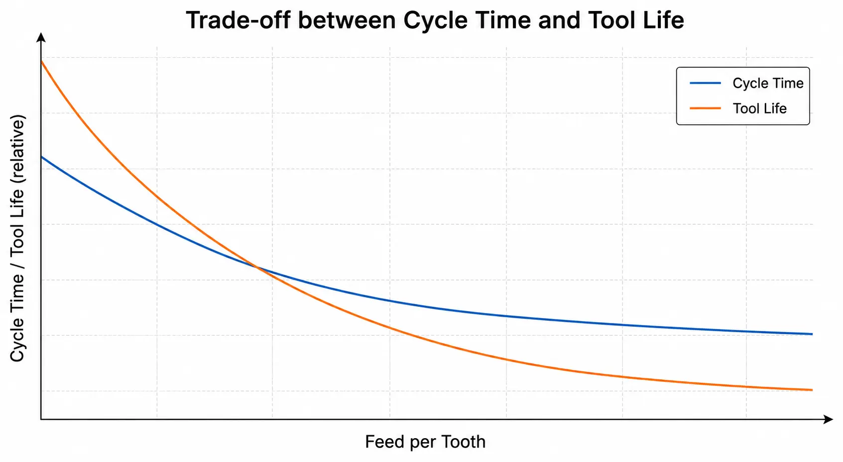
The chosen carbide end mill feed per tooth directly creates a trade-off between speed and tool life. A higher FPT increases the Material Removal Rate (MRR), shortening cycle times and boosting output.[11] However, it also increases heat and pressure, accelerating tool wear and raising the risk of premature failure.
Dive Deeper: Making the Right Business Decision
When a customer asks me, "What's the best feed per tooth?" my follow-up question is always, "What is your primary goal for this operation?" The "best" FPT is different for a high-volume automotive part than it is for a one-off aerospace prototype. The right choice is a business decision, not just a technical one.
The Case for Speed: Maximizing Throughput
In high-volume production environments, time is money. Shaving even a few seconds off a cycle time, repeated over thousands of parts, leads to massive gains in throughput and profitability.
- Goal: Produce as many parts as possible in a given shift.
- Strategy: Run an aggressive carbide end mill feed per tooth, pushing it towards the upper end of the recommended range.
- Trade-off: You accept that tools will wear out faster. Tooling is treated as a predictable consumable cost. The increased output more than pays for the higher tool consumption.
This approach is all about maximizing the Material Removal Rate (MRR), which is calculated as:
MRR = Radial DOC x Axial DOC x Feed RateSince
Feed Rate is directly tied to FPT, a higher FPT leads to a higher MRR and shorter cycle time.The Case for Tool Life: Minimizing Cost and Risk
In other scenarios, such as job shops, prototyping, or when machining expensive and difficult materials, the cost of a single tool or a scrapped workpiece is a major concern.
- Goal: Ensure process security, avoid breaking expensive tools, and achieve a perfect part on the first try.
- Strategy: Run a conservative carbide end mill feed per tooth, starting at or even slightly below the manufacturer's recommendation.
- Trade-off: Cycle times will be longer. The priority is preserving the tool and ensuring the part is made correctly, which avoids the much higher costs associated with tool failure and scrap. This is especially true when using large, complex, or custom-made carbide tools where the replacement cost is high.
As a supplier, we often advise customers in this situation to start conservatively. Listen to the cut, examine the chips, and then incrementally increase the FPT by 5-10% at a time. This methodical process helps them find their own operation's economic sweet spot without unnecessary risk.
Finding the "Sweet Spot": The Total Cost Equation
The most advanced shops don't just choose speed or tool life; they find the optimal balance where the total cost per part is lowest. This involves considering:
- Machining Time Cost: Your machine's hourly rate. Longer cycles cost more.
- Tooling Cost: The cost of the end mill divided by the number of parts it can produce.
The true "sweet spot" for your carbide end mill feed per tooth is the point where the combination of these two costs is at its minimum. This is the essence of process optimization and the question we love helping our customers solve.
Frequently Asked Questions
What is the difference between feed per tooth (FPT) and feed rate?
Feed per tooth (FPT), or chip load, is the thickness of the material that each cutting edge (flute) of the tool removes per revolution. Feed rate is the overall speed of the tool's movement across the workpiece, usually measured in inches per minute (IPM) or millimeters per minute (mm/min). The feed rate is calculated from the FPT.
Can I use the same feed per tooth for roughing and finishing?
No, you should use different values. Roughing operations prioritize high material removal, so a higher FPT is used. Finishing operations prioritize surface quality, which requires a much lighter chip load. Therefore, a significantly lower FPT is used for finishing passes to achieve a smooth, accurate surface.
What happens if my feed per tooth is too low?
Contrary to popular belief, a feed per tooth that is too low can be just as damaging as one that is too high. It causes the cutting edges to rub against the material instead of cleanly shearing a chip.[12] This rubbing action generates excessive heat, causes work hardening in the material, and leads to chatter and rapid tool wear.
How do I know if I need to adjust my feed per tooth?
Listen to the cut and inspect the chips. A stable, smooth humming sound is good; a loud, violent squeal or chatter means the cutting forces are wrong. Ideal chips are typically "C" or "9" shaped and have a light straw to brown color. Powdery or dusty chips indicate rubbing (FPT is too low). Dark blue or purple chips indicate excessive heat (FPT or RPM is too high).
Conclusion
Ultimately, discovering the optimal carbide end mill feed per tooth is a process of informed adjustment, not a search for a single magic number. By understanding that manufacturer charts are starting points, you can begin to make intelligent decisions. The real skill lies in balancing the key variables—material, tool geometry, and depth of cut—with your specific business goals, whether they are maximum throughput or minimum risk. This strategic approach transforms a simple machining parameter into a powerful tool for improving your operational efficiency and profitability.
At QT TOOLS, we don't just sell tools; we partner with you to find the most effective and economical solutions for your unique challenges. If you're looking to optimize your machining process and reduce your cost-per-part, contact our expert team today. We are committed to helping you find the right starting point and the perfect tool for your application.
1
"Helical - MACHINING GUIDEBOOK", https://web.mae.ufl.edu/designlab/Advanced%20Manufacturing/Helical_Machining_Guidebook.pdf. A machining reference explains that feed per tooth, or chip load, is selected in relation to cutting speed, cutter geometry, workpiece material, and the intended operation, supporting the article's treatment of FPT as a calculated starting point rather than a universal constant. Evidence role: general_support; source type: education. Supports: A university or machining-text reference should support that milling feed per tooth is selected from cutting conditions and tool/workpiece parameters rather than from a universal value..
2
"common milling speeds (rpm)", https://machineshop.olin.edu/files/machine-shop/files/mill_commons_chart_draft4.pdf. A machining education source describes speed-and-feed tables as recommended values derived from tool and work-material conditions and notes that they must be adapted to the actual machine setup, which supports this claim about manufacturer charts as starting guidance. Evidence role: general_support; source type: education. Supports: A neutral machining source should state that feeds and speeds are selected using tool geometry, work material, and operation conditions and are commonly adjusted from recommended starting values..
3
"An Investigation of Cutting Tool Chatter Vibration in Machine Tools", https://scholarworks.uni.edu/cgi/viewcontent.cgi?article=4664&context=grp. Research on machining dynamics identifies limited machine-tool stiffness as a contributor to regenerative chatter and links chatter with poor surface finish and accelerated tool wear, supporting the article's warning about rigidity-dependent vibration. Evidence role: mechanism; source type: paper. Supports: A peer-reviewed paper should explain that low dynamic stiffness or rigidity in machine-tool systems contributes to regenerative chatter and degraded machining outcomes..
4
"Tool Run-Out in Micro-Milling: Development of an Analytical ...", https://pmc.ncbi.nlm.nih.gov/articles/PMC10972115/. Studies of end-milling runout show that radial eccentricity changes the instantaneous chip thickness assigned to each tooth, producing unequal tooth loading and helping explain premature wear or breakage risks. Evidence role: mechanism; source type: paper. Supports: A research source should support that radial runout changes the instantaneous chip thickness taken by individual cutter teeth..
5
"Comparison of Tool Wear, Surface Roughness, Cutting Forces ...", https://pmc.ncbi.nlm.nih.gov/articles/PMC10303288/. Machining-wear literature reports that harder work materials and abrasive phases increase contact stress and abrasive wear at the cutting edge, supporting the need to reduce chip load in difficult materials. Evidence role: mechanism; source type: paper. Supports: A tribology or machining paper should explain how workpiece hardness and abrasive constituents increase tool wear or edge loading..
6
"Stainless Steel Work Hardening: Causes and Machining ...", https://yumoparts.com/en/resources/blog/what-is-stainless-steel-work-hardening. Materials-processing references note that many stainless steels, especially austenitic grades, work-harden during machining and that feed is a major contributor to cutting force, providing contextual support for conservative FPT selection in stainless steels. Evidence role: mechanism; source type: research. Supports: A materials or machining source should support that austenitic stainless steels can work-harden during machining and that feed affects cutting force.. Scope note: The source may support the work-hardening tendency and feed-force relationship generally rather than prescribing the exact table adjustment.
7
"Compensation for Deflection of Miniature Milling Tools", https://pec.ncsu.edu/research/compensation-for-deflection-of-miniature-milling-tools/. Engineering beam theory states that the area moment of inertia of a circular section increases with the fourth power of diameter, which provides the mechanical basis for the greater rigidity of larger-diameter end mills under comparable loading. Evidence role: mechanism; source type: education. Supports: An engineering mechanics or machining source should show that bending stiffness increases strongly with diameter, reducing deflection under cutting load.. Scope note: This is a mechanics-based explanation and does not account for all cutter-design differences such as flute depth, length of cut, or carbide grade.
8
"Do 3-Flute End Mills Really Dominate Aluminum?", https://www.ksptg.com/learning/3-flute-end-mills-aluminum/. Manufacturing references on end-mill geometry explain that increasing flute count generally reduces chip-gullet volume per flute, which can constrain chip evacuation and affect feed selection. Evidence role: mechanism; source type: education. Supports: A manufacturing education source should explain the trade-off between number of flutes and chip space in milling cutters.. Scope note: The claim is geometry-dependent; specialized high-flute tools may use designs that partly mitigate reduced chip space.
9
"Feedrates For the Milling Machine", https://www.youtube.com/watch?v=h_kXgwMe-IU. A standard machining reference defines milling table feed as the product of spindle speed, feed per tooth, and the number of cutter teeth, confirming the formula used here. Evidence role: definition; source type: education. Supports: A machining reference should define table feed as spindle speed multiplied by chip load per tooth and number of teeth/flutes..
10
"Radial Chip Thinning – How to Max Out Your Milling Tool ...", https://www.dapra.com/articles/radial-chip-thinning. Research on radial chip thinning in milling shows that low radial immersion reduces maximum chip thickness relative to the programmed feed per tooth, requiring feed compensation and often lowering engagement-related cutting loads. Evidence role: mechanism; source type: paper. Supports: A research paper should explain radial chip thinning and the effect of low radial immersion on chip thickness and feed-rate compensation.. Scope note: The source may support chip-thinning and force trends generally; the magnitude of any permissible FPT increase depends on cutter geometry, material, and machine dynamics.
11
"Material Removal Rate [Optimizing MRR for Bigger Profits]", https://www.cnccookbook.com/material-removal-rate-optimizing-mrr-for-bigger-profits/. Machining references define milling material removal rate as the product of feed rate, axial depth of cut, and radial width of cut; because feed rate depends on feed per tooth, higher FPT can increase MRR and reduce cutting time when other variables remain fixed. Evidence role: definition; source type: education. Supports: A machining source should define MRR as a function of feed rate and depth/width of cut, and feed rate as dependent on FPT.. Scope note: This relationship is conditional because machine power limits, chatter, chip evacuation, and tool wear may prevent a proportional productivity gain.
12
"Estimation of Minimum Uncut Chip Thickness during Precision and ...", https://pmc.ncbi.nlm.nih.gov/articles/PMC8745993/. Minimum-chip-thickness studies show that when uncut chip thickness falls below a threshold, the cutting edge increasingly ploughs or rubs instead of forming a chip, raising heat generation and accelerating wear. Evidence role: mechanism; source type: paper. Supports: A peer-reviewed machining source should describe minimum chip thickness and the transition from shearing to ploughing or rubbing when feed is too low.. Scope note: The exact threshold depends on edge radius, tool material, work material, and cutting conditions.