
Aug 6, 2026Technical Blog & Machining Tips
What Makes a Good Extra Long Carbide End Mill?

Struggling with machining deep pockets and complex cavities? You likely know the frustration of an extra long carbide end mill snapping mid-operation, scrapping an expensive workpiece and bringing production to a halt. You've tried different brands and coatings, but the costly failures persist. The solution isn't about finding a marginally better tool; it's about understanding that the tool's fundamental geometric design is the only thing standing between a successful part and a catastrophic loss.
A good extra long carbide end mill is defined by its geometric design features that increase rigidity and improve chip evacuation[1], not just its length or coating. Key design elements like a reinforced core, variable helix angles, and optimized flute shapes are crucial for preventing the vibration, deflection, and catastrophic tool breakage common in deep-pocket machining.
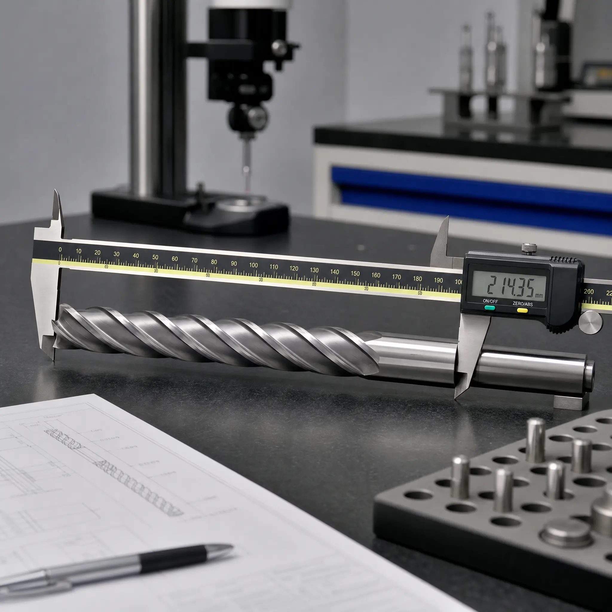
Now that we've established that geometry is the most critical factor, you might be wondering which specific design features matter most. Let's dive deeper into the physics behind why these tools fail and what separates a reliable tool from a costly liability. This knowledge will empower you to make smarter procurement decisions that protect your bottom line.
Why Does a Longer End Mill Fail More Often?
You've probably noticed that when you switch from a standard-length tool to a longer one, problems like chatter, poor surface finish, and outright tool breakage suddenly appear. It can feel like you're fighting a losing battle, with each new tool investment leading to more scrap and downtime. The root cause isn't a defect in the tool itself, but a fundamental principle of engineering: rigidity is lost exponentially as length increases[2].
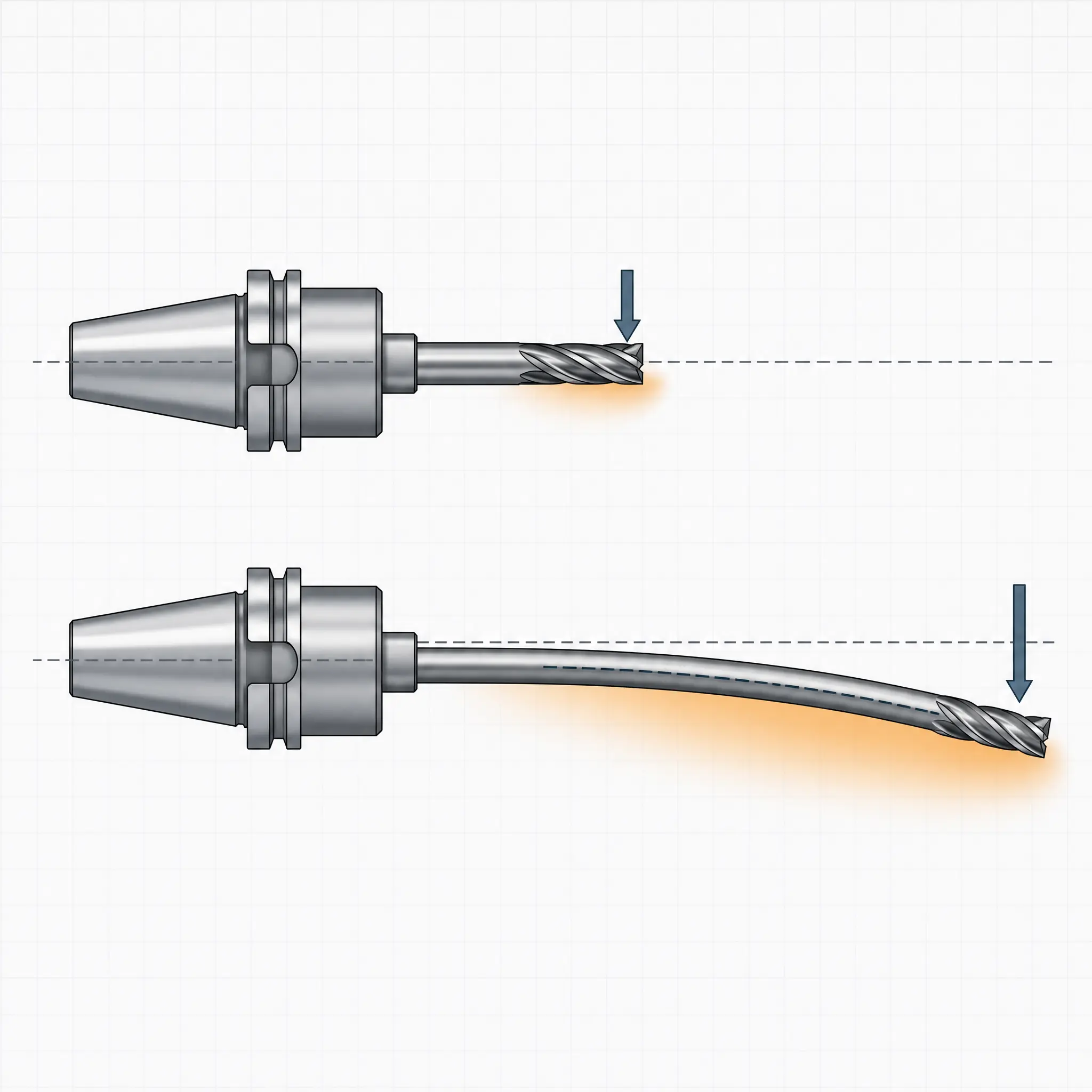
Longer end mills fail more often because their increased length-to-diameter ratio dramatically reduces their rigidity[3]. This makes them highly susceptible to bending and vibration (chatter) under normal cutting forces[4], which leads to dimensional inaccuracies, poor surface finish, and ultimately, catastrophic tool failure.
Dive Deeper: The Physics of Failure
Think of an extra long carbide end mill like a diving board. A short board is stiff and stable. A long diving board, however, is flexible and wobbly. The same exact force applied to both will cause the long board to bend and oscillate far more. This is precisely what happens inside your CNC machine. The cutting forces that a standard tool handles with ease become a major problem for a long tool.
This relationship is often described by the length-to-diameter (L:D) ratio. In our internal failure analysis labs, we consistently see a spike in tool failures when the L:D ratio exceeds 5:1 for general-purpose tools. Pushing beyond 8:1 without specialized geometry is inviting disaster.
The loss of rigidity causes two primary problems:
- Deflection: The tool physically bends away from the workpiece under load. Even a microscopic bend can have significant consequences, leading to out-of-spec dimensions, tapered walls in what should be a straight pocket, and a poor surface finish.[5]
- Vibration (Chatter): As the tool deflects and springs back, it can enter a state of harmonic vibration, commonly known as chatter[6]. This is the high-pitched squeal you sometimes hear during a cut. Chatter is not just an annoying sound; it's the signature of a tool rapidly hammering itself and the workpiece to pieces.
The business consequences of low rigidity are severe and costly:
- Scrapped Workpieces: A snapped tool can instantly destroy a part that may already have hours of machine time and thousands of dollars invested in it.
- Machine Downtime: Replacing a broken tool, reprogramming the machine, and verifying the setup takes time. At a machine hour rate of 200, even a short stoppage adds up.
- Reduced Tool Life: Constant vibration causes the cutting edges to chip and wear out prematurely, forcing you to buy replacement tools more frequently.
- Unpredictable Processes: When tool failure is unpredictable, it becomes impossible to run "lights-out" manufacturing or plan production schedules with any confidence.
Understanding this core problem is the first step. The next is realizing that advanced coatings can't fix a tool that is fundamentally unstable.
Is Geometry More Important Than Coating for an Extra Long Carbide End Mill?
Many tool suppliers emphasize their advanced coatings, suggesting that a high-tech layer of TiAlN or AlCrN is the key to performance. You invest in these premium-priced tools, hoping they will solve your breakage issues. Yet, you may find that the expensive, coated extra long carbide end mill still shatters, leaving you to question the value of the coating itself. The truth is, you're focusing on the wrong feature.
Yes, for an extra long carbide end mill, its core geometry is profoundly more important than its coating. A tool with poor geometry will vibrate and deflect regardless of how advanced its coating is. The geometry provides the fundamental stability and chip control required for the cutting edge—and its coating—to perform effectively. Putting an expensive coating on a poorly designed tool body is like putting performance tires on a car with a bent frame.

Dive Deeper: The Hierarchy of Tool Design
A coating's primary job is to function at the micro-level of the cutting edge. It reduces friction, acts as a thermal barrier, and increases surface hardness to resist abrasive wear.[7] These are all incredibly valuable benefits, but they only work if the cutting edge is presented to the workpiece in a stable, consistent manner.
If the tool body is vibrating due to poor geometric design, the cutting edge is slamming into the material unpredictably. This impact loading will cause the coating to chip and flake away[8], rendering it useless. The tool then fails due to the underlying lack of rigidity, not because the coating wore out.
From my experience in R&D, here are the geometric features that truly determine the success or failure of an extra long carbide end mill:
H3: Critical Geometric Features for Rigidity and Control
- Core Diameter: The core is the backbone of the end mill. A thicker core dramatically increases the tool's stiffness and resistance to bending.[9] The best designs for long tools often feature a core that tapers, becoming thicker toward the shank for maximum support, or a reinforced shank design.
- Helix Angle: Standard helix angles (like 30°) are fine for general use, but they can create a consistent cutting rhythm that leads to harmonic vibrations in long tools. A variable helix or differential pitch design changes the angle along the flute or between flutes. This breaks up the cutting rhythm, disrupting the harmonics and suppressing chatter before it can build to a destructive level.
- Chip Gullets (Flutes): In deep pockets, getting chips out is as important as the cut itself. If chips pack into the flutes, they can cause the tool to bind and snap.[10] Well-designed long-reach tools have highly polished, deep, and precisely shaped gullets that actively guide and eject chips up and out of the cavity.
To put it simply, geometry and coatings have different jobs. Both are important, but they operate in a clear hierarchy.
Feature | Primary Role in Long-Reach Milling | Consequence of Poor Design |
|---|---|---|
Geometry | Provides rigidity, controls vibration, evacuates chips | Catastrophic tool breakage, scrapped workpiece |
Coating | Reduces friction, resists heat and abrasive wear | Premature edge wear, slightly shorter tool life |
As you can see, the consequences of poor geometry are immediate and catastrophic, while the consequences of a lesser coating are more gradual. You must solve the geometry problem first.
How Do You Calculate the True Cost of an Extra Long Carbide End Mill?
Your procurement department is focused on one number: the unit price. They see a tool from Supplier A for 80, and the decision seems obvious. You, however, know the pain of watching that 5,000 mold core. The challenge is communicating that the cheapest tool is often the most expensive choice.
The true cost of an extra long carbide end mill is not its purchase price. It is the unit price plus the total potential cost of failure. This includes the value of a scrapped workpiece, lost machine time, labor for rework, and the cascading impact of delayed deliveries. A well-designed, more reliable tool is a form of inexpensive insurance.

Dive Deeper: The "Total Cost of Failure" Framework
When you frame the purchasing decision around risk, the entire equation changes. A slightly higher initial investment in a properly engineered tool becomes an obviously smart business decision. Let's run the numbers on a common scenario.
Scenario: Machining a deep pocket in a P20 tool steel mold component.
- Workpiece Value: The raw material and previous machining operations have put $5,000 of value into the part.
- Machine Hour Rate: The CNC machine costs $150/hour to operate.
- Tool Options:
- Tool A: A generic extra long carbide end mill for $50.
- Tool B: A geometrically optimized extra long carbide end mill for $80.
Now, let's say the cheap Tool A snaps mid-cut, destroying the part.
Calculating the Total Cost of Failure:
- Value of Scrapped Workpiece: +$5,000
- Machine Downtime (2 hours to clean up, reset, and re-run): 2 x 300
- Cost of the Failed Tool: +$50
- Total Financial Loss: $5,350
In this light, the decision is clear. You could have spent an extra 5,350 loss. The "expensive" tool is actually the cheapest option because it mitigates the single largest cost driver: catastrophic failure.
H3: Shifting the Procurement Mindset
To get this message across to management and purchasing, you need to speak their language. Move the conversation away from "tool price" and toward "production reliability" and "risk management."
Start by asking questions that quantify the problem within your own facility:
- "What is our current scrap rate on jobs that require deep pocketing?"
- "How much machine downtime did we log last month due to broken long-reach tools?"
- "What is the average value of the workpieces we are scrapping in these operations?"
By attaching real financial data from your own operations to the problem, you transform the purchase of a quality extra long carbide end mill from an expense into a strategic investment in profitability and predictability.
What Questions Should You Ask a Supplier About Their Extra Long Carbide End Mill Design?
Every sales representative will tell you their tools are "high-performance" and "top-quality." These marketing terms are useless for making a sound technical and financial decision. You need a way to cut through the noise and assess whether a supplier truly understands the engineering challenges of long-reach milling or if they are just selling a commodity.
Instead of asking about price, you should ask a supplier specific questions about how their extra long carbide end mill design addresses the fundamental problems of low rigidity and chip evacuation. This forces a technical discussion that quickly separates the engineering experts from the mere distributors.

Dive Deeper: The Smart Buyer's Questionnaire
Arming yourself with the right questions shifts the power dynamic. You are no longer a passive buyer; you are an informed evaluator. Based on my years of designing these tools, here are the questions I would ask any potential supplier:
- "How is the core of this long-reach end mill designed to maximize rigidity and prevent vibration?"
- A Good Answer Looks Like: "We use a tapered core that increases in diameter towards the shank, which significantly stiffens the tool body. For our ultra-long series, we use a reinforced shank diameter to further combat deflection."
- A Bad Answer Looks Like: "It's made from high-quality carbide." (This doesn't address the geometry).
- "Do you use a variable helix or differential pitch on this tool? If so, why?"
- A Good Answer Looks Like: "Yes, we use a 38/42 degree variable helix. This design disrupts the constant-frequency vibrations that lead to chatter in deep cuts, allowing for a smoother finish and higher material removal rates without risking tool failure."
- A Bad Answer Looks Like: "It has a standard 30-degree helix. It's the industry standard." (This shows a lack of specialization for long-reach applications).
- "What specific features are incorporated into the flute design to ensure effective chip evacuation from deep cavities?"
- A Good Answer Looks Like: "The flute gullets are not only deep but also have a highly polished surface finish to reduce friction. Their shape is computer-optimized to actively curl the chip and propel it out of the pocket, preventing chip packing."
- A Bad Answer Looks Like: "It has four flutes for a good finish." (This is a generic statement that doesn't address the unique challenge of deep pockets).
- "Can you provide any cutting parameter recommendations or test data for using this tool in [Your Material] at an L:D ratio of 8:1?"
- A Good Answer Looks Like: "Absolutely. Here is a starting recipe for speeds and feeds in P20 steel. We recommend reducing the radial engagement to 5% of the diameter to minimize tool pressure and control deflection. We have a case study I can share."
- A Bad Answer Looks Like: "You'll have to figure that out on your machine." (This shows a lack of application support and expertise).
A supplier who can answer these questions with confidence and technical detail is a partner. A supplier who cannot is just a reseller. Your job is to find partners who can help you solve problems, not just sell you products.
Frequently Asked Questions
What is the maximum L:D ratio for a carbide end mill?
This is highly dependent on the tool's specific geometric design, the material being cut, and the machining strategy. While general-purpose end mills often struggle beyond a 5:1 ratio, high-performance tools designed specifically for long-reach applications can perform successfully at 8:1, 10:1, or even higher ratios when paired with the correct, conservative cutting parameters.
Can I just reduce my cutting speed and feed rate for a long end mill?
Yes, reducing your speeds, feeds, and depth of cut is mandatory when using any long end mill. However, it is not a magic fix. A tool with poor geometry will still be prone to vibration and failure, even at very slow parameters. A well-designed tool allows you to run at more productive, yet still safe, parameters, ultimately saving time and money.
What's the difference between a long-reach and an extended-shank end mill?
A long-reach end mill has a long cutting length (flutes) that matches its overall reach. An extended-shank or "necked" end mill has a standard, shorter cutting length, but the shank behind the flutes is reduced in diameter. This allows the tool to reach deep into a cavity without the non-cutting part of the shank rubbing against the walls of the pocket.
Is a solid carbide extra long end mill always better than an indexable one?
For finishing, semi-finishing, and applications where dimensional accuracy and surface finish are paramount, a solid carbide tool is almost always superior. Its monolithic design provides better balance, rigidity, and runout accuracy. Indexable long-reach tools are generally better suited for heavy roughing in larger-diameter applications where the ability to quickly replace a worn insert is more important than achieving a perfect finish.
Conclusion
Selecting the right extra long carbide end mill is far more than a simple line-item purchase; it's a critical risk management decision for your entire manufacturing operation. The key takeaway is to shift your focus from brand names and coatings to the fundamental engineering that prevents failure. A well-designed tool, defined by its rigidity-enhancing geometry, is the most effective insurance against the immense costs of scrapped parts and production downtime. By learning to calculate the true cost of failure and asking suppliers the right technical questions, you can transform your procurement process from a cost center into a source of competitive advantage.
At QT TOOLS, we have dedicated over a decade to the research and design of carbide tools that solve these exact challenges. Our expertise is built on countless hours of internal testing and failure analysis. If you're struggling with reliability in your deep-pocket machining operations, contact our team. We can help you evaluate your specific application and recommend an extra long carbide end mill engineered for stability, predictability, and performance.
1
"Mechanics and dynamics of general milling cutters.: Part I: helical end mills", https://www.sciencedirect.com/science/article/abs/pii/S0890695501000451. A machining-research source should be cited to show that end-mill geometry influences tool stiffness, cutting stability, and chip evacuation, which contextualizes the article’s emphasis on geometry over length alone. Evidence role: general_support; source type: paper. Supports: End-mill geometry, including core, flute, and helix design, affects stiffness, cutting stability, and chip evacuation in milling.. Scope note: The source may support the general relationship between geometry and performance rather than evaluating this specific extra-long carbide end mill design.
2
"BEAM DEFLECTION FORMULAS", https://home.engineering.iastate.edu/~shermanp/STAT447/STAT%20Articles/Beam_Deflection_Formulae.pdf. An engineering mechanics source should be cited for the cantilever-beam relationship showing that deflection under load scales strongly with unsupported length, providing the mechanical basis for the reduced rigidity of longer end mills. Evidence role: mechanism; source type: education. Supports: Cantilever-beam deflection increases with the cube of unsupported length under comparable loading, explaining why longer tools are much less rigid.. Scope note: This is contextual mechanical support; an end mill is not a perfect uniform cantilever beam during cutting.
3
"Tool Length-Dependent Stability Surfaces", https://mtrc.utk.edu/wp-content/uploads/sites/45/2019/09/tool_length_stability.pdf. A milling-dynamics study should be cited to support that increasing tool overhang or length-to-diameter ratio reduces tool stiffness and increases susceptibility to deflection during cutting. Evidence role: mechanism; source type: paper. Supports: In milling, increased tool overhang or length-to-diameter ratio reduces static and dynamic stiffness and increases deflection risk.. Scope note: The evidence will usually address tool overhang or L:D ratio broadly, not every end-mill brand or geometry.
4
"An Investigation of Cutting Tool Chatter Vibration in Machine ...", https://scholarworks.uni.edu/cgi/viewcontent.cgi?article=4664&context=grp. A machining-dynamics source should be cited to show that limited tool stiffness under cutting forces increases the likelihood of tool deflection and chatter in milling. Evidence role: mechanism; source type: paper. Supports: Reduced tool stiffness and cutting forces contribute to regenerative chatter and vibration in milling operations..
5
"The form error prediction in side wall machining considering tool deflection", https://www.academia.edu/27229692/The_form_error_prediction_in_side_wall_machining_considering_tool_deflection. A manufacturing-research paper should be cited to support that end-mill deflection contributes to dimensional inaccuracies, wall-form errors, and reduced surface finish quality. Evidence role: general_support; source type: paper. Supports: Tool deflection in end milling can cause dimensional error, wall form error, and poorer surface finish..
6
"Machining vibrations", https://en.wikipedia.org/wiki/Machining_vibrations. A technical encyclopedia or machining-dynamics source should be cited to define chatter as an unstable vibration phenomenon in machining, often associated with regenerative effects during cutting. Evidence role: definition; source type: encyclopedia. Supports: Chatter in machining is a vibration phenomenon associated with unstable cutting dynamics, often described as regenerative or self-excited vibration.. Scope note: An encyclopedia source is appropriate for definition but would not by itself quantify failure risk for a specific tool.
7
"Characterization and Evaluation of Engineered Coating Techniques for ...", https://pmc.ncbi.nlm.nih.gov/articles/PMC9415707/. A review article on hard coatings for cutting tools should be cited to support that such coatings can reduce friction, improve thermal or oxidation resistance, and increase wear resistance at the cutting edge. Evidence role: general_support; source type: paper. Supports: Hard coatings for cutting tools can reduce friction, improve hot hardness or oxidation resistance, and reduce abrasive wear.. Scope note: The source may describe coating behavior generally and not prove performance in the specific long-reach milling scenario discussed.
8
"Comparison of Lifetime of the PVD Coatings in Laboratory ...", https://pmc.ncbi.nlm.nih.gov/articles/PMC7254225/. A cutting-tool coating failure study should be cited to support that mechanical impact and cyclic loading can promote coating cracking, chipping, or delamination during machining. Evidence role: mechanism; source type: paper. Supports: Mechanical impact, cyclic loading, or unstable cutting conditions can contribute to coating cracking, chipping, or delamination on cutting tools.. Scope note: The source may identify plausible coating-failure mechanisms rather than directly testing chatter in extra-long end mills.
9
"Stability Analysis and Structure Optimization of Unequal-Pitch End ...", https://pmc.ncbi.nlm.nih.gov/articles/PMC8618622/. An engineering mechanics source should be cited to support that increasing cross-sectional diameter increases bending stiffness, providing the mechanical rationale for a thicker end-mill core resisting deflection. Evidence role: mechanism; source type: education. Supports: For a round or near-round tool body, bending stiffness increases strongly with cross-sectional diameter through the area moment of inertia.. Scope note: This source supports the mechanics of diameter and stiffness; actual end-mill stiffness also depends on flute geometry and material.
10
"Cutting Load Capacity of End Mills with Complex Geometry", https://research.sabanciuniv.edu/231/1/3011800000736.pdf. A machining study or technical reference should be cited to support that inadequate chip evacuation can cause chip accumulation, increased cutting resistance, and greater risk of tool failure in milling. Evidence role: mechanism; source type: paper. Supports: Chip accumulation or inadequate chip evacuation in milling can increase cutting resistance, clog flutes, and contribute to tool failure.. Scope note: The source may discuss chip evacuation generally rather than documenting the exact sequence of flute packing followed by snapping.