
Sep 20, 2026Technical Blog & Machining Tips
Spindle Speeds for Endmills: What's the Right Choice?
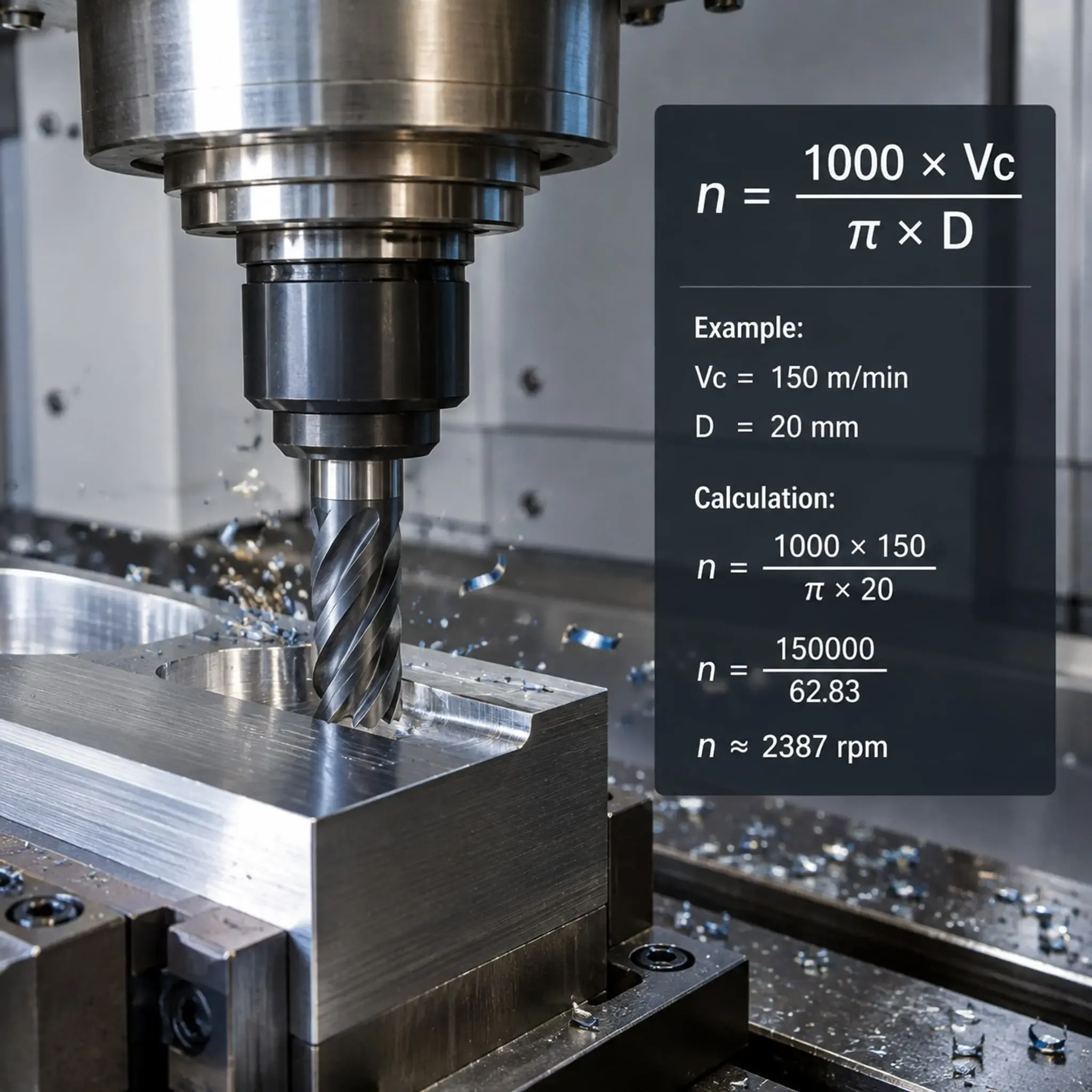
When it comes to spindle speeds for endmills, many buyers expect a simple chart or universal formula. Here's the reality: selecting spindle speeds is not like choosing one fixed number; it's a balancing act that considers material properties, tool life, and overall machining efficiency. The optimal spindle speed depends on specific machine setups, workpiece materials, tool designs, and operational goals.[1] Let’s explore how to make smarter decisions for your machining operations.
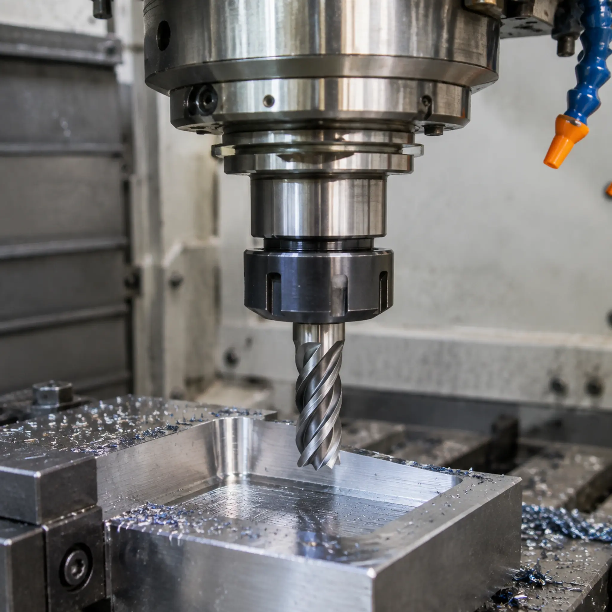
Generic recommended speeds only scratch the surface. To truly optimize for quality, cost, and reliability, we need to go beyond static numbers. Let's dig into the details below.
Why don’t spindle speed charts cover all scenarios?
Many machining operations start with a speed and feed chart. The problem? These charts provide a generic starting point, not a definitive answer.[2]
Spindle speed settings vary wildly across machining setups. Factors like machine rigidity, endmill coating, coolant application, and even workpiece size play critical roles. Misinterpreting charts often costs operations critical productivity.
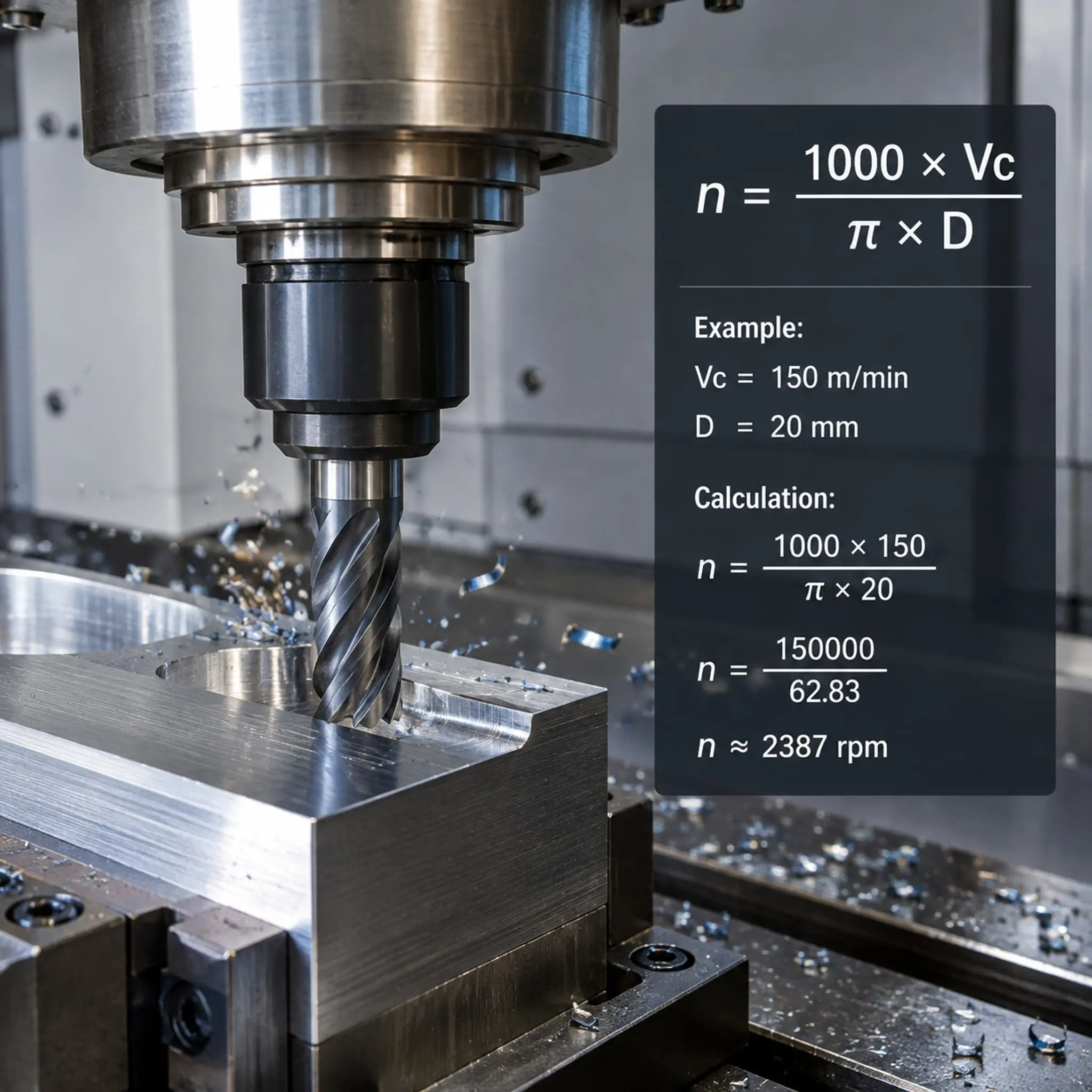
Digging deeper into speed chart limitations
Speed charts assume ideal conditions—perfectly rigid machines, exact workpiece hardness, and premium tooling. However, real-world shop floors are dynamic environments. Here’s where factory settings and assumptions may diverge from reality:
- Machines with lower rigidity[3] demand reduced speeds to prevent vibration or tool deflection.
- Exotic materials like nickel alloys or titanium[4] don’t behave like mild steel and need smaller adjustments per pass.
- Tool coating[5], whether general-purpose or high-performance, influences heat resistance and material removal rates.
Take this scenario: One client working with hardened steel struggled with frequent tool breakage despite following industry-average speeds. Adjusting parameters based on their actual machine setup solved the issue, extending tool life threefold.
Achieving the best outcome requires testing—not just relying on charts as the sole source of truth.
What really matters when choosing spindle speeds?
Knowing the spindle speed isn’t enough—you need to understand your machining priorities. Ask yourself: What's the primary goal of running this endmill in your operation?
Goals can vary:
- Maximizing productivity: Push speeds higher to reduce cycle times in large production volumes.[6]
- Achieving best surface finish: Lower speeds paired with precise feed rates minimize micro-defects[7] for aesthetics or high-precision requirements.
- Extending tool life: Conservative speeds prevent wear[8] and maximize ROI on expensive carbide tools.
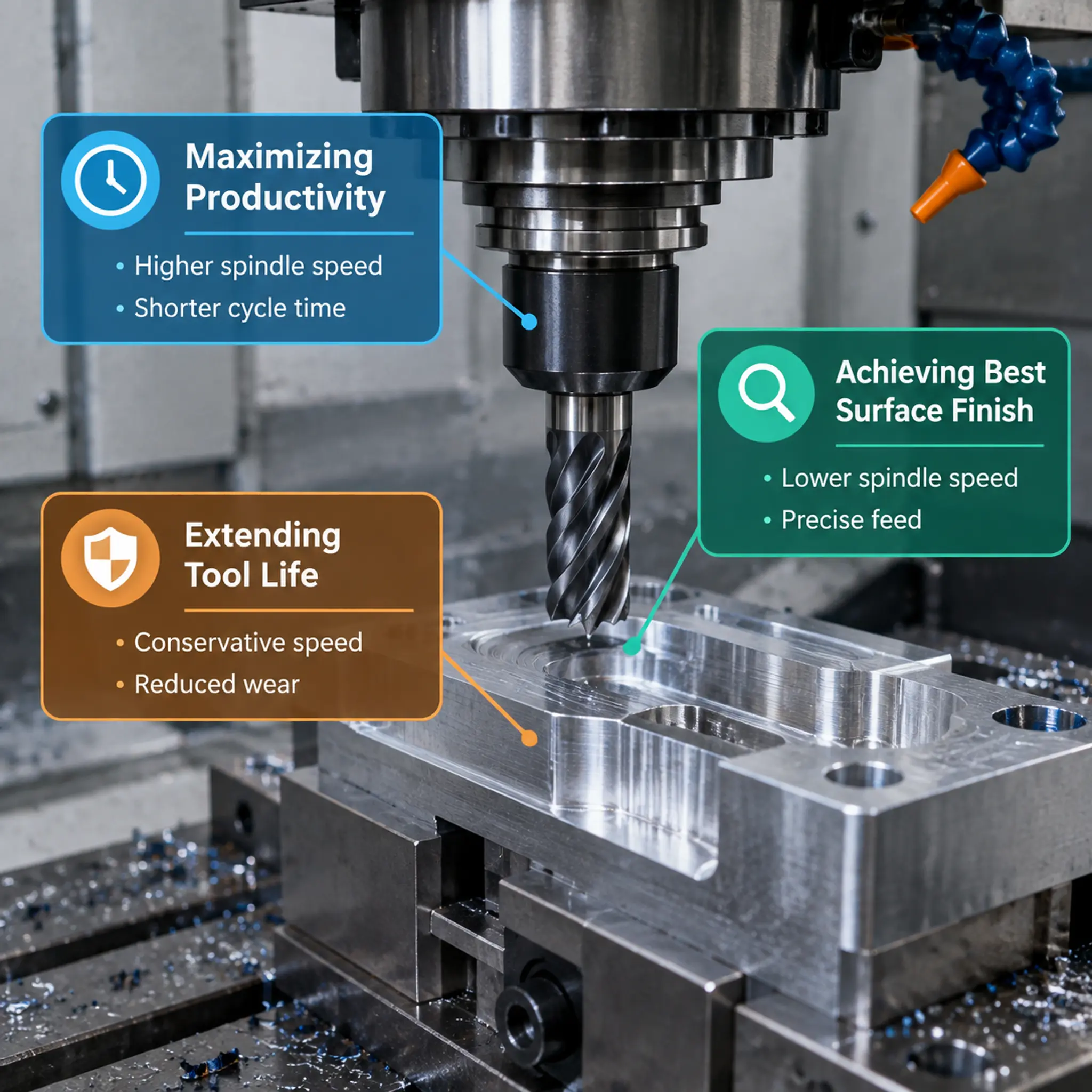
Build a scenario-based parameter strategy
Most issues arise when spindle speed decisions fail to meet the operation’s true priority. For example:
- High-output automotive shops may favor faster settings to maximize throughput.
- Precision aerospace contractors often reduce speeds for finer tolerances and defect-free results.
- Prototyping operations balance across all outcomes, testing increments both ways to find middle-ground efficiency.
Structured questions like this help in focus:
- “Are production costs or product quality my bigger risk?”
- “What’s my risk tolerance for minor tool damage?”
- “Am I testing results often enough to fine-tune settings?”
Being clear about priority prevents rushed mistakes that slow lucrative job orders.
How do I adjust spindle speeds for real-world conditions?
One major shift involves treating spindle speeds as dynamic parameters rather than fixed “set-it-and-forget-it” values. Here’s a decision-making framework for buyers and operators:
1. Start with the manufacturer’s recommendation
Every reputable supplier provides initial guidelines tailored to their tools. For carbide endmills, RPM values will vary depending on tool diameter and material hardness. Starting here helps avoid wild guesswork.
2. Listen for chatter and inspect chips
Chatter during machining indicates instability[9]—reduce spindle speeds and adjust feed rates until sounds smooth out. Similarly, inspect chips regularly:
- Bright, uniform chips mean optimal cutting.
- Burnt or discolored chips point to overheating[10]—slow spindle speeds.
- Dust-like chips may mean speeds are too high for the material.
3. Make incremental adjustments
Once settings stabilize, tweak speeds gradually (no more than +/- 10%)[11]. Collaborate with QC teams to measure cutting outcomes methodically. Avoid excessive changes, as they often worsen performance rather than improve it.
4. Factor process health
Buyer inquiries often focus on material and tool specs, skipping how external variables impact spindle speed outcomes:
- Tool holder quality: Poor alignment amplifies vibrations.[12] High-quality holders prevent speed errors from compounding.
- Coolant application: Generates heat stability, allowing faster speeds without burning edges or coatings.
- Machine maintenance: Worn spindles struggle under demanding RPM changes, reducing machining reliability.
Every tiny adjustment helps bridge the gap between theoretical specs and real-world results.
How can suppliers help refine spindle speeds?
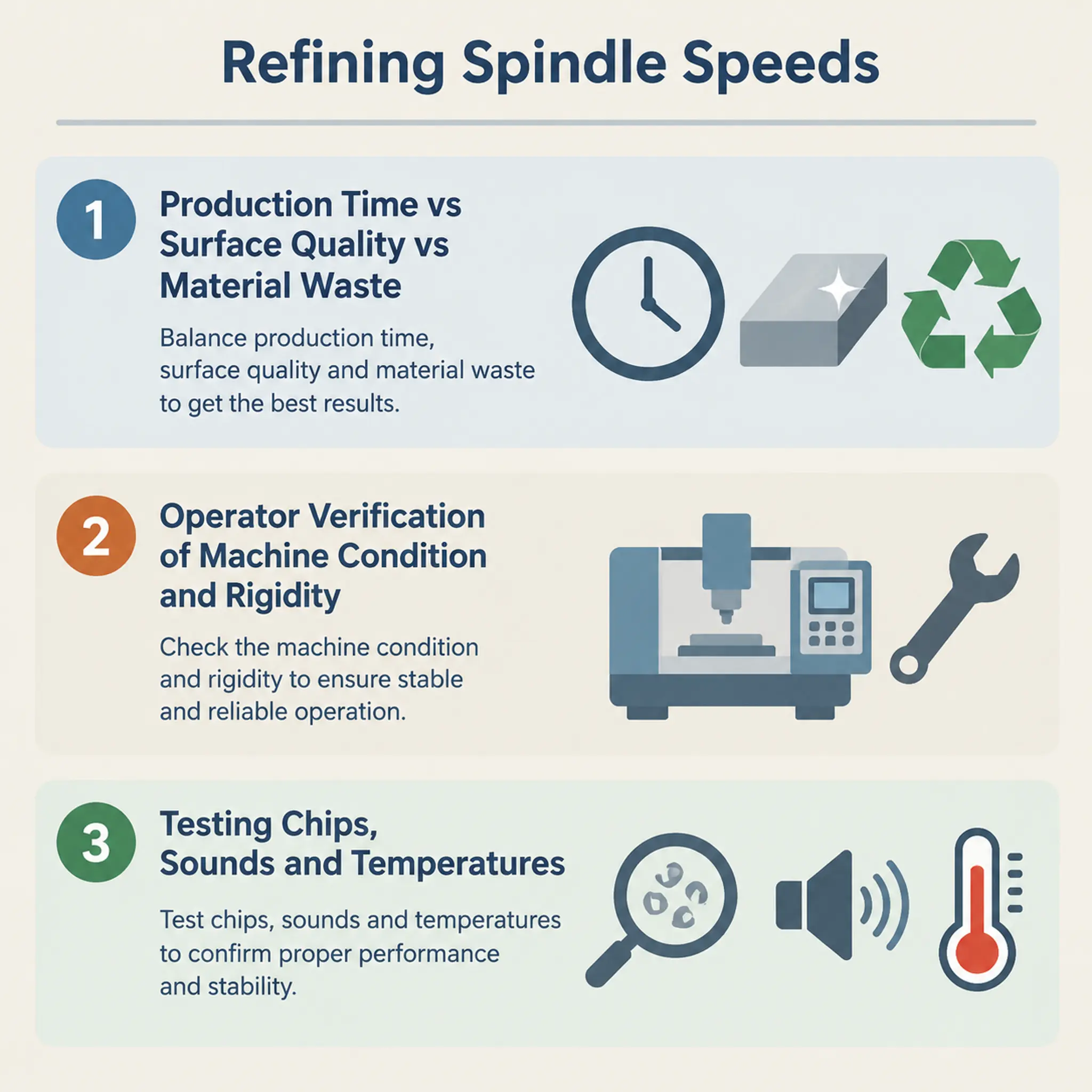
As a tool supplier, I often hear, “Can you just give me the speed number for this material?” Instead of defaulting to charts, we prioritize guidance through these three considerations:
- What matters more: production time, surface quality, or reducing material waste?
- Has the operator verified machine condition and rigidity?
- Would specific testing on chips, sounds, and temperatures reduce risks further?
The role of a trustworthy supplier isn’t just selling tools—it’s simplifying complex machining setups by narrowing risks.
Frequently Asked Questions
Does spindle speed make a difference in tool life?
Yes, spindle speed directly impacts tool life by affecting wear rate. Slower speeds minimize edge degradation, but they also reduce cutting efficiency. A balance between speed and feed is essential—overloading tools damages coatings prematurely.
What is chatter during machining?
Chatter is the vibration or noise that occurs during unstable machining. It often indicates spindle speeds are too high or materials aren’t properly clamped. Adjust speeds downward until vibrations fade.
Can coolant improve spindle speeds?
Absolutely. Proper coolant application minimizes heat buildup during high-speed machining, preventing tool damage and allowing slightly higher spindle speeds. Ensure coolant application is consistent and direct to the cutting zone.
Conclusion
Choosing spindle speeds for endmills isn’t about finding a perfect RPM number on a chart—it’s a process of balancing material properties, operational priorities, and real-world conditions. Spindle speed optimization starts with guidelines but flourishes through adjustments based on chatter, chips, and parameters unique to your shop floor. For buyers, discussing scenarios with a supplier before purchase reduces risks and saves costs downstream.
At QT TOOLS, we combine our carbide endmill expertise with real-world customer insights, providing you with advice tailored to your operations. Ready to optimize your machining process? Reach out to us today!
1
"Speeds and Feeds", https://web.mae.ufl.edu/designlab/Advanced%20Manufacturing/Speeds%20and%20Feeds/Speeds%20and%20Feeds.htm. Manufacturing engineering references describe spindle-speed selection as a function of cutting speed, tool diameter, tool material, workpiece material, and machine or process constraints; this supports the claim as a general machining principle rather than proving an optimum for any specific setup. Evidence role: general_support; source type: education. Supports: Spindle speed selection depends on machine, tool, workpiece, and process constraints.. Scope note: Contextual support; it does not establish a single optimal RPM for the article's specific endmills or customers.
2
"(PDF) Feeds and Speeds Tutorial for CNC - Academia.edu", https://www.academia.edu/31937751/Feeds_and_Speeds_Tutorial_for_CNC. Manufacturing texts commonly present feeds-and-speeds tables as recommended starting values that must be adjusted for tool condition, workpiece material, machine capability, and cutting conditions; this supports the article's caution but does not validate any particular chart. Evidence role: expert_consensus; source type: education. Supports: Published feeds-and-speeds tables are initial recommendations that require adjustment for actual machining conditions.. Scope note: Contextual support; it addresses how charts are used generally, not the accuracy of a specific chart.
3
"[PDF] An Investigation of Cutting Tool Chatter Vibration in Machine Tools", https://scholarworks.uni.edu/cgi/viewcontent.cgi?article=4664&context=grp. Research on machine-tool dynamics links structural stiffness and damping to machining stability, showing that lower rigidity can increase vibration and chatter risk under cutting loads; this supports the mechanism behind reducing speeds in less rigid setups. Evidence role: mechanism; source type: paper. Supports: Lower machine-tool stiffness increases susceptibility to vibration, chatter, or deflection during cutting..
4
"[PDF] TigerPrints - Clemson OPEN", https://open.clemson.edu/cgi/viewcontent.cgi?article=1027&context=auto_eng_pub. Materials and manufacturing literature identifies titanium alloys and nickel-based superalloys as difficult-to-machine materials because of factors such as low thermal conductivity, work hardening, high strength at temperature, and tool-wear tendencies; this supports the need for different speed and feed choices. Evidence role: general_support; source type: research. Supports: Titanium and nickel-based alloys have machining characteristics that differ from mild steels and influence cutting parameters..
5
"[PDF] PERFORMANCE OF COATED CUTTING TOOLS IN MACHINING", http://conferences.sta.uwi.edu/iconetech2020/documents/RSRevuru-PERFORMANCEOFCOATEDCUTTINGTOOLSINMACHINING.pdf. Studies of coated cutting tools report that coating composition and structure can alter oxidation resistance, hardness, friction, and tool wear under high-temperature machining conditions; this supports the article's statement that coatings influence performance. Evidence role: mechanism; source type: paper. Supports: Cutting-tool coatings can affect wear, heat resistance, friction, and allowable cutting performance..
6
"Speeds and Feeds", https://web.mae.ufl.edu/designlab/Advanced%20Manufacturing/Speeds%20and%20Feeds/Speeds%20and%20Feeds.htm. Manufacturing-process references derive milling time from feed rate, which is linked to spindle speed, number of teeth, and feed per tooth; this supports the statement that higher speeds can reduce cycle time when other constraints permit. Evidence role: mechanism; source type: education. Supports: For milling, material removal and machining time are related to feed rate, spindle speed, feed per tooth, and tool engagement.. Scope note: Contextual support; higher speed does not always reduce total cycle time if feed, tool life, stability, or non-cutting operations become limiting.
7
"[PDF] Effect of Machining Feed on Surface Roughness in Cutting 6061 ...", https://open.clemson.edu/cgi/viewcontent.cgi?article=1060&context=auto_eng_pub. Experimental studies on end milling commonly find that feed rate, cutting speed, tool geometry, and vibration influence surface roughness and surface integrity; this supports the link between parameter control and micro-defect reduction. Evidence role: mechanism; source type: paper. Supports: Cutting speed and feed rate influence surface roughness and surface integrity in milling.. Scope note: Contextual support; the best direction of speed adjustment depends on material, tool geometry, vibration, and cutting regime.
8
"(PDF) Physics-guided logistic classification for tool life modeling and ...", https://mtrc.utk.edu/wp-content/uploads/sites/45/2021/06/physics-guided-logistic-classification.pdf. Tool-life literature, including the Taylor tool-life relationship and later empirical studies, identifies cutting speed as a dominant variable affecting wear rate and tool life; this supports the claim that conservative speeds can reduce wear. Evidence role: mechanism; source type: paper. Supports: Cutting speed is a major factor in tool wear and tool life, as described by tool-life models and machining experiments.. Scope note: Contextual support; overly low speeds can create other process problems, so the source would not imply that lower speed is always optimal.
9
"[PDF] Chatter Stability of Machining Operations", https://mtrc.utk.edu/wp-content/uploads/sites/45/2020/08/manu_142_11_110801.pdf. Technical sources on machining dynamics define chatter as a self-excited vibration associated with unstable cutting, supporting the article's identification of chatter as an instability signal. Evidence role: definition; source type: government. Supports: Chatter is a vibration phenomenon associated with instability in machining..
10
"(PDF) A Review on Heat Generation in Metal Cutting", https://www.academia.edu/44060728/A_Review_on_Heat_Generation_in_Metal_Cutting. Machining education resources often explain that chip discoloration results from heat-related oxidation and can be used as a qualitative indicator of cutting temperature; this supports the diagnostic use of burnt or discolored chips. Evidence role: mechanism; source type: education. Supports: Chip color can reflect heat and oxidation conditions generated during cutting.. Scope note: Contextual support; chip color is a qualitative sign and is affected by material, coolant, lighting, and oxidation behavior.
11
"Optimization of Forming Parameters in Incremental Sheet ...", https://pmc.ncbi.nlm.nih.gov/articles/PMC8876622/. Machining training materials and process-optimization guidance commonly recommend controlled incremental changes when refining cutting parameters so that effects on chatter, finish, and tool wear can be isolated; this supports the gradual-adjustment principle. Evidence role: general_support; source type: education. Supports: Machining parameters are commonly refined through controlled incremental adjustments rather than large changes.. Scope note: Contextual support; the exact 10% figure may be a shop-rule heuristic unless a source specifically validates that threshold.
12
"[PDF] AN EXAMINATION OF SURFACE LOCATION ERROR AND ...", https://mtrc.utk.edu/wp-content/uploads/sites/45/2019/09/SLE_ext_abstract.pdf. Research on milling runout and tool-holder dynamics shows that misalignment can produce uneven tooth loading and increased vibration, supporting the article's statement that poor alignment amplifies vibration. Evidence role: mechanism; source type: paper. Supports: Tool-holder runout or misalignment can increase dynamic loading, vibration, and uneven cutting in milling..