
Jul 2, 2026Case Studies & Applications
Is a Longer Reach Carbide End Mill Always the Best Solution?
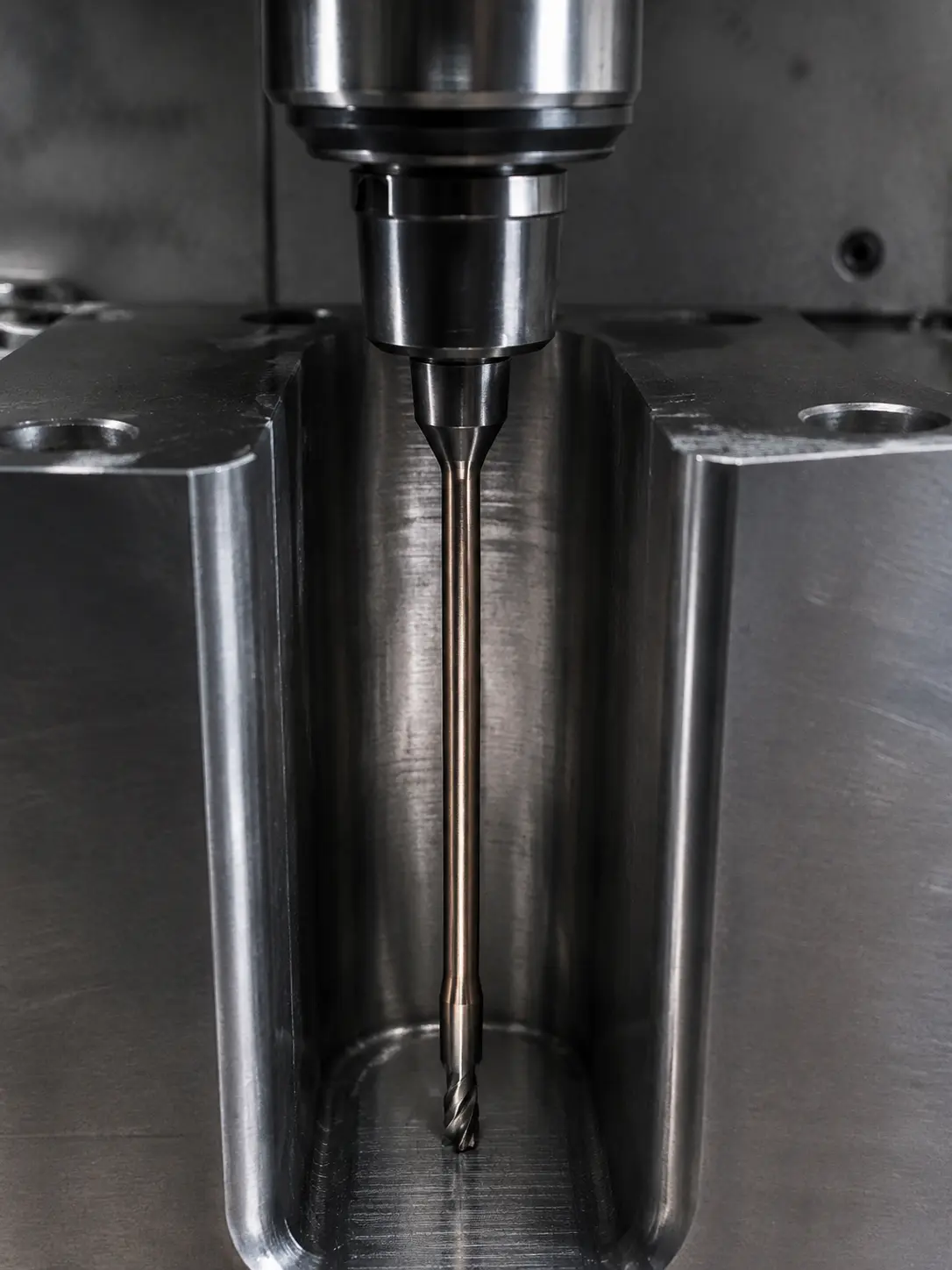
Machining a deep pocket is tough. Using a standard end mill won't work, but you worry a longer one will just snap. You need a better strategy, not just a longer tool.
A long reach carbide end mill is not always best. The right choice is the shortest possible reach that provides the necessary clearance and depth.[1] This simple rule minimizes vibration, deflection, and the risk of tool breakage[2], giving you more stability and better part quality.
I've been in this business for over a decade, and I've seen a common pattern in workshops. There's a strong temptation to buy the longest end mill possible, thinking it can handle any job that comes through the door. It seems like a smart way to save money on tooling. But in reality, this approach often leads to more problems, like broken tools, scrapped parts, and wasted time. The real secret to using long reach tools is not about finding the longest one, but about understanding how to use the shortest one that can possibly do the job. Let's break down how to make the right choice and avoid those costly mistakes.
How Does Reach Affect Tool Stability and Risk?
You bought a long end mill to reach a deep feature on a part. But now you are fighting constant vibration, terrible chatter, and a poor surface finish. Understanding how length destroys rigidity is the key.
A longer reach drastically reduces tool rigidity. The more a tool sticks out from the holder, the more it acts like a lever, amplifying cutting forces into vibration and deflection.[3] This directly increases the risk of chipping, breakage, and inaccurate parts.
Think about pushing on the end of a long, thin stick versus a short, thick one. The long stick bends easily. Your end mill behaves in exactly the same way. In machining, we call this "deflection." The longer the tool, the more it will deflect or bend under cutting pressure. This small bend can quickly turn into a rapid vibration, which we call chatter. Chatter is the enemy of good machining. It leaves a terrible surface finish, puts extreme stress on the cutting edges, and can cause the tool to chip or even snap in an instant.[4]
The goal should always be to use the absolute minimum tool length that can access the feature. This isn't just a suggestion; it's a fundamental principle for stable machining. A shorter, more rigid setup allows you to run at more optimal speeds and feeds, leading to better productivity and longer tool life.[5]
Here is a simple table to show the difference:
Feature | Shortest Practical Reach | Excessively Long Reach |
|---|---|---|
Rigidity | High | Low |
Deflection | Minimal | High |
Vibration Risk | Low | High |
Tool Life | Predictable & Longer | Unpredictable & Shorter |
Surface Finish | Good | Poor (Chatter Marks) |
Breakage Risk | Low | High |
As you can see, choosing a tool that is longer than necessary is not a safe bet—it's a gamble. You are trading a little bit of perceived versatility for a lot of risk.
What's the Difference Between Reach Length, Flute Length, and Overall Length?
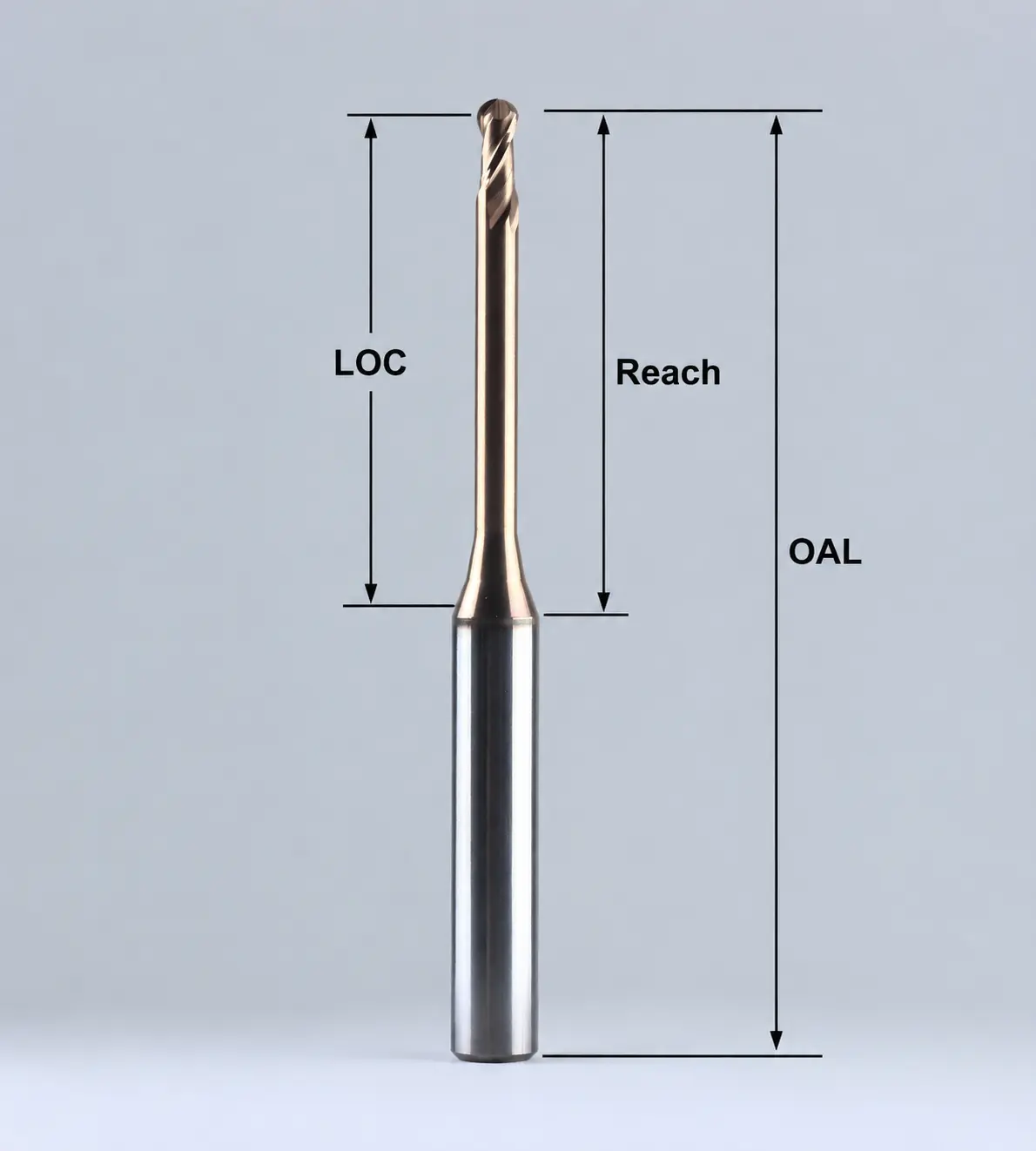
You see "LOC," "OAL," and "reach" on a tool's spec sheet. It can be confusing. Choosing the wrong dimension can lead to packed chips, a broken tool, or a scrapped part. Let's clarify these critical terms.
Flute Length (or Length of Cut) is the cutting edge. Reach Length is the distance from the holder to the cut, often with a reduced neck for clearance. Overall Length is the tool's total length.[6] Matching these correctly is vital for performance.
In my experience, one of the biggest mistakes customers make is confusing these dimensions. They are not interchangeable, and getting them right is the key to using a long reach tool successfully. Let's break them down one by one.
The Key Dimensions
- Overall Length (OAL): This is the easiest one. It's the total measurement from the very tip of the tool to the end of the shank. Its main purpose is to ensure the tool will fit in your machine's tool holder and tool changer without causing a collision.
- Flute Length / Length of Cut (LOC): This is the part of the tool with the cutting edges, the flutes. This is the only part that should be doing any cutting. A critical mistake we often see is using a tool with a very long flute length when only making a shallow cut. This is a bad idea because longer flutes mean less material in the core of the tool, making it weaker and more prone to vibration[7]. Your flute length should be just long enough for your deepest cut, and no more.
- Reach Length: This is what makes a "long reach" end mill special. It is the functional length that can reach into a cavity or past an obstacle. It is often achieved with a "reduced neck" or "undercut shank" design. This means the shank diameter is smaller than the cutting diameter, but there are no flutes on it. This design is brilliant because it gives you the clearance you need to avoid hitting the part wall, while maintaining more strength than a fully fluted section would. The solid neck is much more rigid than a fluted section of the same diameter.[8]
The perfect setup involves using these dimensions intelligently. You want the shortest possible Flute Length for the job, a strong reduced neck for clearance, and the minimum Reach Length necessary to get the job done without the tool holder hitting the workpiece.
How Do I Select the Right Long Reach End Mill for My Job?
You know you need a long reach tool to machine a specific part. But you also know that the wrong choice could scrap the part and destroy a costly tool. Let's walk through a simple, logical process.
To choose correctly, you must first define the job. You need to know the material, the exact depth and clearance required, and the type of machining operation (like roughing or finishing). Only then can you select the right tool.
Before we at the factory can even begin to recommend a tool, we have a list of questions we have to ask. These are the same questions you should be asking yourself in your workshop before you even open a catalog or browse a website. Getting this information first will save you a huge amount of guesswork and prevent expensive mistakes.
Your Pre-Selection Checklist
1. What is the Material and Its Hardness?
This is always the first question. Machining soft aluminum is completely different from machining hardened D2 tool steel. The material dictates the carbide grade we need to use, the geometry of the cutting edge (like the helix angle), and the type of coating that will work best to resist heat and wear.[9] A tool designed for steel will perform poorly in aluminum, and vice versa.[10]
2. What is the Machining Operation?
Are you trying to remove a large amount of material quickly (roughing), or are you trying to create a beautiful, accurate surface (finishing)?
- Roughing: For roughing, you need strength above all else.[11] This means you want a tool with a strong core, which usually means fewer flutes (e.g., 3 or 4) and the shortest possible flute length.
- Finishing: For finishing, stability and edge count are key. A tool with more flutes (e.g., 5 or more) can give a better surface finish, but only if the setup is rigid.[12] Deflection is your enemy here, as it will lead to inaccurate part dimensions.
- Slotting: Cutting a full-width slot puts 180 degrees of engagement on the tool, generating a lot of heat and force. Using a long reach end mill for deep slotting is extremely risky and should be avoided if possible. It is much better to use side milling (trochoidal milling) strategies.
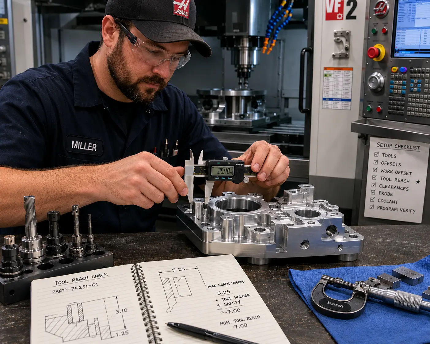
3. What is the Exact Clearance Requirement?
Get out your calipers. You need to know two things precisely:
- Z-Depth: How deep is the pocket or feature you need to machine? This determines the minimum Length of Cut (LOC) you need.
- X/Y Clearance: How deep can the tool go before the tool holder hits the workpiece or a clamp? This determines your maximum Reach Length.
Only after you have the answers to these three questions can you confidently choose a tool. The mission is to find a tool where the flute length just covers your Z-depth, and the reach length is just enough to clear any obstacles. This is the true path to success with long reach end mills.
Conclusion
Choosing the right long reach tool is not about maximizing length; it's about managing risk. Use the shortest practical reach to ensure stability, improve tool life, and produce quality parts.
At QT Tools, we help you match or customize the perfect carbide end mill for your specific material, depth, and operation, delivering the quality and performance you need to succeed.
1
"[PDF] Helical - MACHINING GUIDEBOOK", https://web.mae.ufl.edu/designlab/Advanced%20Manufacturing/Helical_Machining_Guidebook.pdf. A manufacturing-engineering reference explains that reducing tool overhang increases stiffness and helps control vibration in milling, supporting the article's rule to use only the reach needed for clearance rather than excess length. Evidence role: expert_consensus; source type: education. Supports: A machining or manufacturing-engineering source should support that minimizing tool overhang or reach improves rigidity and process stability.. Scope note: The source may discuss tool overhang generally rather than long-reach carbide end mills specifically.
2
"Research on the influence of cutter overhang length on robotic ...", https://pmc.ncbi.nlm.nih.gov/articles/PMC11496886/. Studies of milling dynamics report that increased cutter overhang reduces dynamic stiffness and makes the system more susceptible to deflection and chatter, which provides a mechanical basis for linking shorter reach with lower breakage risk. Evidence role: mechanism; source type: paper. Supports: A peer-reviewed study should show that increased tool overhang lowers dynamic stiffness and increases vibration or deflection during milling.. Scope note: The source may directly measure vibration or deflection, while breakage risk is inferred from the increased cutting-edge stress and instability.
3
"[PDF] BEAM DEFLECTION FORMULAS", https://home.engineering.iastate.edu/~shermanp/STAT447/STAT%20Articles/Beam_Deflection_Formulae.pdf. Cantilever-beam theory states that end deflection increases strongly with beam length under a given load, providing the mechanical analogy for why longer tool stickout amplifies cutting-force deflection. Evidence role: mechanism; source type: encyclopedia. Supports: A mechanics source should explain that deflection of a cantilever beam increases strongly with length under load.. Scope note: The beam model is a simplified analogy and does not capture all effects of rotating-tool geometry, holder compliance, or cutting dynamics.
4
"Influence of Axial Depth of Cut and Tool Position on Surface Quality ...", https://pmc.ncbi.nlm.nih.gov/articles/PMC8836450/. Research on machining chatter identifies self-excited vibration as a cause of poor surface quality and elevated tool wear, supporting the article's warning that chatter can damage cutting edges and compromise the part. Evidence role: mechanism; source type: paper. Supports: A machining-dynamics paper should support that chatter worsens surface quality and increases tool wear or tool failure risk.. Scope note: The source may document wear and surface finish more directly than sudden tool snapping, which depends on tool material, engagement, and process parameters.
5
"[PDF] Chatter Stability of Machining Operations Dedicated to S.A. Tobias ...", https://academy.cba.mit.edu/classes/computer_machining/chatter.pdf. Machining-stability literature shows that higher tool-workpiece system stiffness increases the range of stable cutting conditions, which can permit more productive feeds and speeds and reduce instability-related tool wear. Evidence role: expert_consensus; source type: paper. Supports: A source on machining stability should support that higher structural stiffness expands stable cutting conditions, enabling more productive feeds and speeds.. Scope note: Tool life also depends on coating, material, coolant, and cutting parameters, so stiffness alone does not guarantee longer life.
6
"The Anatomy of an End Mill - In The Loupe", https://www.harveyperformance.com/in-the-loupe/end-mill-anatomy/. Machining nomenclature references distinguish overall length from length of cut or flute length and from reach-related clearance dimensions, supporting the article's explanation that these specifications are not interchangeable. Evidence role: definition; source type: education. Supports: A machining education source should define overall length, length of cut or flute length, and reach-related dimensions used in end-mill selection.. Scope note: Terminology for 'reach length' can vary among catalogs and standards, so the source may use a closely related term such as neck length or usable length.
7
"Tech Tip: Reducing Chatter & Vibration in End Milling - Kennametal", https://www.kennametal.com/us/en/resources/blog/metal-cutting/reducing-chatter-and-vibration-in-end-milling.html. Research on end-mill structural modeling shows that flute geometry and core cross-section influence cutter stiffness and dynamic response, supporting the article's claim that unnecessary flute length can reduce rigidity. Evidence role: mechanism; source type: paper. Supports: A technical source should show that flute geometry and reduced core cross-section affect end-mill stiffness and vibration response.. Scope note: The exact stiffness loss depends on flute design, core diameter, helix angle, and tool material, so the source may support the mechanism rather than a universal numerical rule.
8
"[PDF] Modeling and experimentation for three-dimensional dynamics of ...", https://mtrc.utk.edu/wp-content/uploads/sites/45/2019/09/3D_dynamics.pdf. Structural mechanics and cutter-modeling studies indicate that material removed for flutes reduces the effective cross-section and bending stiffness relative to a solid section, supporting the claim that a solid neck is generally more rigid than a fluted portion of similar outside diameter. Evidence role: mechanism; source type: research. Supports: A source should support that removing material to form flutes reduces cross-sectional area or area moment of inertia, lowering bending stiffness compared with a solid section.. Scope note: The comparison is contextual because actual stiffness also depends on flute depth, helix geometry, neck diameter, and transition radii.
9
"[PDF] PERFORMANCE OF COATED CUTTING TOOLS IN MACHINING", http://conferences.sta.uwi.edu/iconetech2020/documents/RSRevuru-PERFORMANCEOFCOATEDCUTTINGTOOLSINMACHINING.pdf. Manufacturing references describe cutting-tool material, coating, and geometry as choices that depend on workpiece material properties such as hardness, abrasiveness, heat generation, and chip formation behavior. Evidence role: expert_consensus; source type: institution. Supports: A tooling or manufacturing reference should explain that workpiece material properties guide selection of cutting-tool substrate, geometry, and coating.. Scope note: Such references typically provide selection principles rather than prescribing one exact grade or coating for every material.
10
"Can One End Mill Cut Both Aluminum and Inconel?", https://www.ksptg.com/learning/geometry-aluminum-inconel/. Machining education sources note that aluminum and steels differ in chip formation, cutting forces, adhesion tendency, and heat behavior, which is why tools optimized for one material may perform poorly in the other. Evidence role: expert_consensus; source type: education. Supports: A machining source should explain that aluminum and steel often require different cutter geometries, coatings, and chip-evacuation characteristics.. Scope note: The statement is generally true for optimized performance, although some general-purpose tools can machine both materials under conservative conditions.
11
"[PDF] MATERIAL REMOVAL PROCESSES", https://www.egr.msu.edu/~pkwon/me478/machining.pdf. Manufacturing-process references characterize rough milling as a high material-removal operation with larger cutting loads than finishing, supporting the article's emphasis on tool strength during roughing. Evidence role: general_support; source type: education. Supports: A manufacturing source should support that roughing uses higher material-removal conditions and requires robust tools capable of withstanding greater cutting forces.. Scope note: The exact flute count or design choice still depends on material, engagement, tool diameter, and machine rigidity.
12
"Assessment of surface roughness in milling of wood with different ...", https://bioresources.cnr.ncsu.edu/resources/assessment-of-surface-roughness-in-milling-of-wood-with-different-material-temperature-and-cutting-parameters/. Milling surface-finish studies report that cutter geometry, including tooth count, and dynamic stability influence surface roughness, supporting the claim that high-flute finishing tools require a rigid, chatter-resistant setup. Evidence role: mechanism; source type: paper. Supports: A study or machining reference should support that flute count and dynamic stability affect surface roughness in milling.. Scope note: More flutes do not universally improve finish because chip evacuation, radial engagement, feed per tooth, and workpiece material can change the result.